Description
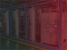
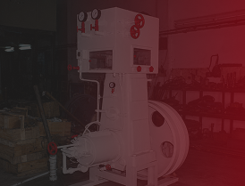
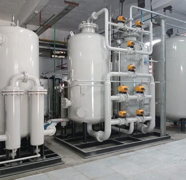
KVK Corporation's Oxygen/Nitrogen Gas Plant is based on cryogenic air separation and is designed to produce Oxygen and Nitrogen in different operating modes. The catalogue highlights high gas purity, low power consumption, stable operation, efficient cooling, liquid Nitrogen withdrawal and cylinder-filling facilities.
Key Features
- Design features enabling simultaneous Oxygen and Nitrogen production.
- Highly efficient Expansion Engine for rapid and adequate cooling.
- High standard of gas purity and low power consumption.
- Special bypass valve for quick production and better cooling.
- Electronic temperature indicating/scanning system.
- Pressure differential gauges and liquid-level indicators with stainless-steel control panel.
- High-quality Perlite insulation to prevent cold losses.
- Liquid Nitrogen withdrawal facility.
- Pump for filling Oxygen with separate Nitrogen pump.
- Heavy-duty four-stage air compressor suitable for diesel-generator or normal 415/440 V, 50-cycle power supply.
- No bulky gas holder required.
- Industrial refrigerator/chilling plant with air-cooling facility before and after the drier battery.
- Low maintenance cost.
- Safe and easy to operate.
- Online Oxygen purity analyser.
- Non-lubricated cross-head liquid pumps for Oxygen pumping.
- Facility for PPM-grade dry Nitrogen gas.
- Minimum Oxygen loss through waste Nitrogen to achieve optimum production.
Technical Data
| Name of the unit | 80 M³/Hr | 150 M³/Hr | 250 M³/Hr | 300 M³/Hr | 400 M³/Hr |
|---|---|---|---|---|---|
| Air Compressor Motor | 150 HP | 215 HP | 340 HP | 450 HP | 300 HP x 2 |
| Expansion Engine Motor | 10 HP | 10 HP | 20 HP | 20 HP | 20 HP |
| Chilling Plant Motor | 3.5 HP | 3.5 HP | 7.5 HP | 7.5 HP | 10 HP |
| Water Pump Motor | 5 HP | 5 HP | 10 HP | 15 HP | 20 HP |
| Cooling Tower Motor | 5 HP | 5 HP | 7.5 HP | 7.5 HP | 10 HP |
| Liquid Oxygen Pump Motor | 5 HP | 7.5 HP | 10 HP | 10 HP | 10 HP |
| Liquid Nitrogen Pump Motor | — | 5 HP | 7.5 HP | 7.5 HP | 7.5 HP |
| Defrosting Heater | 9 KW | 9 KW | 9 KW | 9 KW | 9 KW |
| Molecular Battery Heater | 24 KW | 24 KW | 36 KW | 42 KW | 42 KW |
| Specifications | 80 M³/Hr | 150 M³/Hr | 250 M³/Hr | 300 M³/Hr | 400 M³/Hr |
|---|---|---|---|---|---|
| Cylinder filling manifold (O₂) | 10 x 10 | 15 x 15 | 24 x 24 | 30 x 30 | 32 x 32 |
| Buffer manifold (O₂) | 6 | 6 | 10 | 12 | 12 |
| Cylinder Filling Manifold (N₂) | — | 5 x 5 | 10 x 10 | 10 x 10 | 12 x 12 |
| Cooling Water (re-circulated) | 20 m³/hr | 25 m³/hr | 40 m³/hr | 60 m³/hr | 65 m³/hr |
| Make-up water (Approx.) | 4 m³/day | 5 m³/day | 5 m³/day | 7 m³/day | 8 m³/day |
| Max. Individual item weight | 6 Ton | 7.5 Ton | 10.5 Ton | 11.5 Ton | 14 Ton |
| Gross Weight (Approx.) | 25 Ton | 30 Ton | 40 Ton | 42 Ton | 45 Ton |
| Assembly Height | 9.2 Meter | 9.2 Meter | 9.3 Meter | 9.3 Meter | 9.3 Meter |
| Area required | 200 sq.mtr. | 300 sq.mtr. | 300 sq.mtr. | 400 sq.mtr. | 600 sq.mtr. |
| Power consumption | 1.4 unit/m³ | 1.0 unit/m³ | 0.95 unit/m³ | 1.0 unit/m³ | 1.0 unit/m³ |
Production Data – 150 M³/Hr Reference Plant
Production Cycle – I: Oxygen-gaseous-dry-99.6% and above purity-150 M³/Hr.; Nitrogen-gaseous-96-98% purity - waste product.
Production Cycle – II: Oxygen-gaseous-dry-99.6% and above purity-135 M³/Hr.; Nitrogen-gaseous-99.9% purity-150 M³/Hr. (Nitrogen Compressor required for filling this Nitrogen into Cylinders - at extra cost.)
Production Cycle – III: Oxygen-gaseous-dry-99.6% and above purity-135 M³/Hr.; Nitrogen liquid 20 to 25 Ltrs. Per hour purity 99.9%
Production Cycle – IV: Oxygen-gaseous-dry-99.6% and above purity-125 M³/Hr.; Nitrogen gaseous dry-Less than 10 PPM purity-35 M³/Hr.